Cellular Manufacturing
 Graphics Image by Aberdeen Strategy & ResearchOpens in new window
Cellular Manufacturing is a process of manufacturing which is a subsection of just-in-time (JIT) manufacturing and lean manufacturing encompassing group technologyOpens in new window. |
In traditional manufacturing, products are usually moved from one group of identical machines to another. Typically, machines with identical functions are located together in an area referred to as a department or process.
Workers who specialize in the operation of a specific machine are located in each department. LeanOpens in new window and JIT manufacturingOpens in new window replace this traditional pattern with a pattern of manufacturing cells or work centers where robots supplement people to do many routine operations.
What are Manufacturing Cells?
Manufacturing cells are sets of machines that are grouped by the products or parts they produce in a lean manufacturing environment.
Manufacturing cells contain machines that are grouped in families, usually in a semicircle. The machines are arranged so that they can be used to perform a variety of operations in sequence.
Each cell is set up to produce a particular product or product family. Products move from one machine to another from start to finish.
Workers are assigned to cells and are trained to operate all machines within the cell. Thus, labor in lean manufacturing environment is multifunctional labor, not specialized labor. Each manufacturing cell is basically a minifactory or a factory within a factory.
The lean manufacturing systems are believed to be able to respond sooner to changes in component design and its demand without incurring the cost. Fundamentally the traditional production systems were based on two traditional concepts:
- Job shop system, which is process layout and used for high variety and low volume of products;
- Flow shop system, which is based on a product layout and used for low variety and high volume of products.
In general, job shop systems are believed to obtain maximum flexibility for wide variety of products with small lot sizes. Components manufactured in job shop systems requiring different operations and thus different machine arrangements.
Components are released in batches or jobs, thus tracing homogeneous machines and skilled labors. Hence the machines are grouped depending upon the production process: such as one section is dedicated for milling, other is for grinding, and so on.
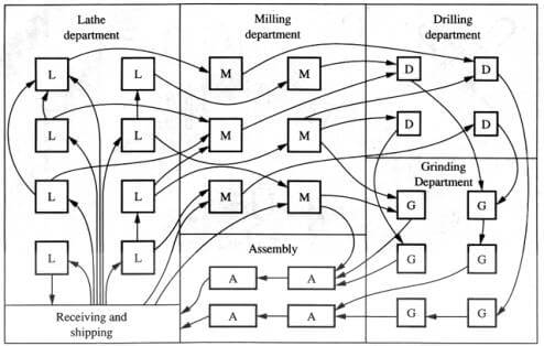 Figure X-1. Job shop layout
|
In job shops, work-in-progress (WIP) is quite high therefore material handling is also high (Askin & Vakharia, 1990). A typical job shop layout is depicted in Figure X-1. If the demand of component mix alters it is assigned to free machines regardless of its families or minimum moves. Hence planning, scheduling and control are tough in such occasion.
On the other hand flow shop system exploits a product layout. Dedicated machines are arranged in queue to produce some component family depending upon their requirements as shown in Figure X-2.
 Figure X-2. Shop floor product layout | Source: Internet.
|
Due to the heavy investment for these specialized machines this layout is only justified when a large volume of the components are being manufactured. The disadvantage of this system is the minimum flexibility therefore lesser variety in production.
To evade the disadvantages of these two systems, more flexible system was proposed by Burbidge (1963, 1975, 1996). This is termed as Cellular Manufacturing System (CMS) which exploits group technology (GT) philosophy developed in the early 1950s (Mitrofanov, 1966).
GT is a metaphysics which states that similar entities should be grouped together. GT is applied in cellular manufacturing as an alternative of traditional manufacturing system. Designing manufacturing cell is usually called cell formation problem (CF/CFP) which consists of the following approaches:
- similar parts are normally grouped into part families according to their processing requirements
- dissimilar machines are grouped to form manufacturing cells and consequently part families are allocated to cells
Depending on the procedures involved in CFP, three solution methodologies are proposed by Selim et al. (1998):
- part families are accomplished first and hence machines are clustered into cells according to the processing requirement of part families. This is known as part-family identification,
- manufacturing cells (clustering of heterogeneous machines) are first generated based on uniformities in part routing and then the part families are allocated to cells. This is known as machine group identification,
- part families and machine cells are formed concurrently, which is known as part families/machine grouping
The main goal of the cellular manufacturing system is to exploit the advantages of flow shop and job shop productions and to reduce their disadvantages (Kusiak, 1987). Closely 30% - 90% of material handling cost could be eliminated by implementing cellular system.
 Figure X-2. Shop floor product layout | Source: Internet.
|
Similar machines are located in adjacent vicinity to each another and granted to produce one or more component families. GT layout is presented in Figure X-2. Thus substantially high production rate close to a flow line could be achieved. It also provides great flexibility in producing an optimum level in variety (Sudhakarapandian, 2007).
CMS has been the most successful mode that today’s firms have adopted to survive in global competition. This novel approach has been adopted in several industries over the past few decades, such as machinery and tools, aerospace and defense, automotive, and electrical (Wemmerlov & Johnson, 1997).
Advantages of Cellular Manufacturing
Once manufacturing cells are formed, the following advantages can be observed.
- Minimizing setup time
A manufacturing cell is designed to produce similar components (similar shape, size, etc.) therefore the manufacture of many parts exploits the same equipment and the setup time is minimized.
- Minimizing lot sizes
The reduction of setup time implies lot sizes to be processed which are more economical. Small lot sizes also help in smooth production.
- Minimizing in-process products and finished goods inventories
Level of Work-in-Progress is proportional to the setup time (Askin & Standridge, 1993) which further enables minimization of the time-to-market.
- Minimizing material handling cost and time
In CMS, component travel time and distance between machines is minimal due to the processing in small cells. Therefore all flows are clustered in one cell, minimizing the flow time.
- Minimizing tooling requirements
Components produced in a cell have same shape, size and composition and generally require same tools.
- Minimizing space required
Reductions in work-in-progress (WIP), finished goods inventories and lot sizes reduces the space required.
- Optimal scheduling and production planning
Scheduling and planning are uncomplicated in CMS, since the manufacturing facility is broken down into manufacturing cells and each component travels in a single cell.
- Improvement in productivity and product quality
Components are produced in a small area and the feedback is instant. Thus, the process can be stopped quickly when things go wrong. Thereafter these advantages depict a clear indication of maximization of the productivity for the firms.
The Lean Techniques:
- Lean Manufacturing Opens in new window
- 5S PrinciplesOpens in new window
- Jidoka: Building Quality into ProductionOpens in new window
- Kaizen: Continuous Change for the BetterOpens in new window
- Kaikaku: Radical ChangeOpens in new window
- The Kanban SystemOpens in new window
- The Manufacturing CellsOpens in new window
- The Poka-Yoke SystemOpens in new window
- Total Productive Maintenance (TPM)Opens in new window
- Visual FactoryOpens in new window
- Lozano, S., Onieva, L., Larraneta, J., & Teba, J. (1993). A neural network approach to part-machine grouping in GT manufacturing. In Proceedings of Robotics (pp. 619 – 624). Mechatronics and Manufacturing Systems.
- Arizono, I., Kato, M., Yamamoto, A., & Ohta, H. (1995). A new stochastic neural network model and its application to grouping parts and tools in flexible manufacturing systems. International Journal of Production Research, 33(6), 1535-1548.
- Arkat, J., Saidi, M., & Abbasi, B. (2007). Applying simulated annealing to cellular manufacturing system design. International Journal of Advanced Manufacturing Technology, 32, 531-536.
- Burke, L., & Kamal, S. (1992). Fuzzy ART for cellular manufacturing. In Proceedings of the Conference on Artificial Neural Networks in Engineering, I, (pp. 779-784).